class: center, middle # MIPS Processor <br /><br /> #### Adi Yoga S. Prabawa.red[*] .footnote[.red[*] email me at dcsaysp (at) nus.edu.sg<br />if you find any bug or you want to work on this] --- # Workspace .left-column[ #### Overview ] .right-column[ .image-100[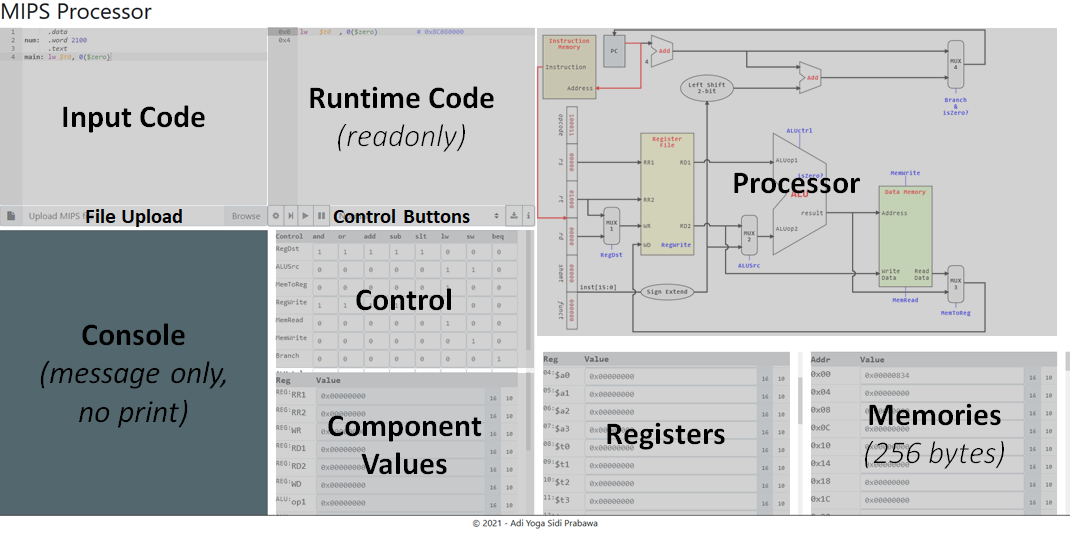] MIPS processor workspace is divided into 10 areas. Please read [MIPS interpreter](_interpreter.html) for Input Code, Runtime Code, File Upload, Control Buttons, Console, Registers and Memories. We will focus on Processor, Control and Component Values. ] --- # Workspace .left-column[ #### Overview #### Processor ] .right-column[ .image-100[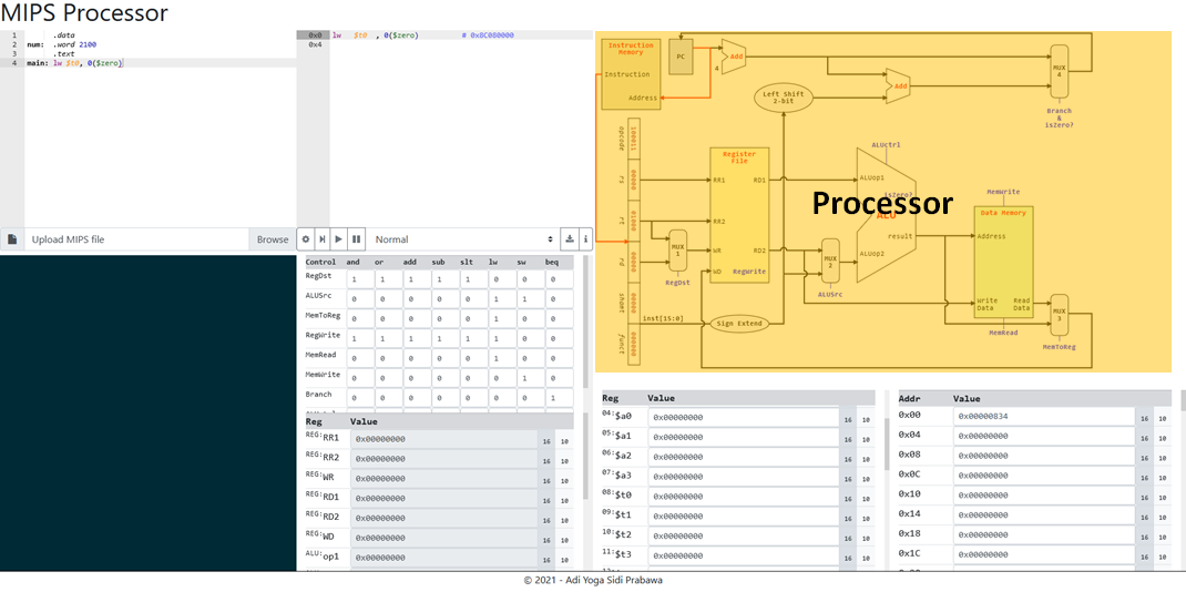] This is a circuit diagram of a simple MIPS processor. Due to its simplicity, it admits a [smaller subset of MIPS instructions](_processor.html#10) than the [MIPS interpreter](_interpreter.html#13). The control lines are coloured blue. ] --- # Workspace .left-column[ #### Overview #### Processor #### Control ] .right-column[ .image-100[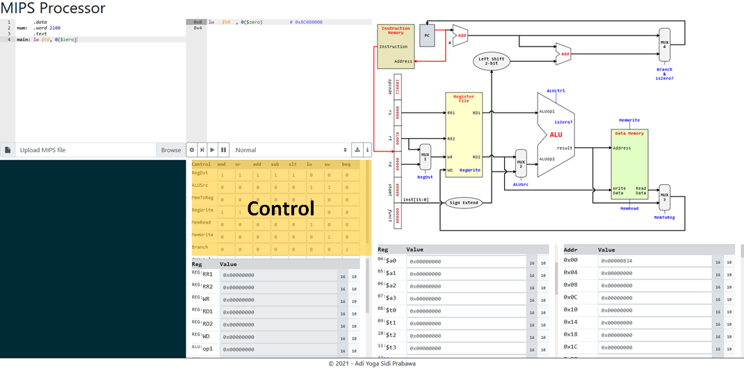] This area contains the values of the control signals for each supported operations. The control lines are coloured blue in the [processor](_processor.html#3). ] --- # Workspace .left-column[ #### Overview #### Processor #### Control #### Component Values ] .right-column[ .image-100[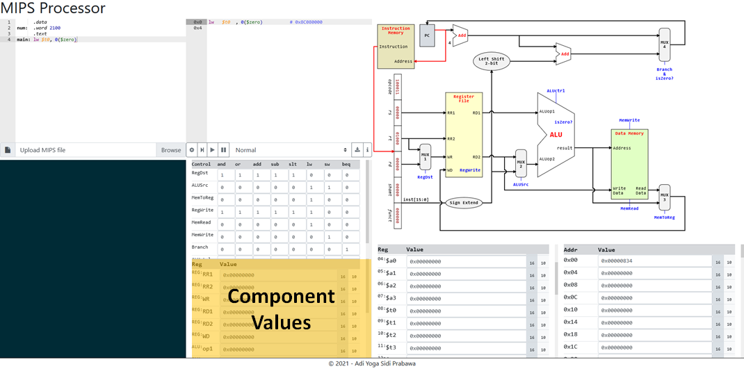] This area contains the values of the relevant components of the processor. This area is ***readonly***. ] --- # Stages .left-column[ #### Overview ] .right-column[ .image-50[] .mediumtext[ The processor implementation follows the 5 stages processor: 1. [Fetch](_processor.html#7) 2. [Decode](_processor.html#8) 3. [Execute](_processor.html#9) 4. [Memory](_processor.html#11) 5. [Writeback](_processor.html#12) The approximate components used are marked in the image above. Pressing a step (<i class="fa fa-step-forward"></i>) stepping one stage at a time. ] ] --- # Stages .left-column[ #### Overview #### Fetch ] .right-column[ .image-75[] .mediumtext[ Fetch the instruction from `Instruction Memory` as binary values. This is the only time the runtime code is accessed. The rest depends on the internal value of the processor as a hardware emulation. ] ] --- # Stages .left-column[ #### Overview #### Fetch #### Decode ] .right-column[ .image-75[] .mediumtext[ Decode the instruction by passing the value to `Register File`, allowing the `Register File` to read the data from the register. `RegDst` values are read for the relevant operation and the write register value is kept for future reference. ] ] --- # Stages .left-column[ #### Overview #### Fetch #### Decode #### Execute ] .right-column[ .image-75[] .mediumtext[ `ALU` executes the operation. The second operand to the `ALU` depends on the value of `ALUSrc` and the operation depends on the `ALUctrl` according to the table on the [next slide](_processor.html#10). ] ] --- # Stages .left-column[ #### Overview #### Fetch #### Decode #### Execute ] .right-column[ ### ALUCtrl <table class="table table-sm"> <thead class="table-secondary"> <tr> <th scope="col">OPCode</th> <th scope="col">ALUctrl</th> <th scope="col">Operation</th> </tr> </thead> <tbody> <tr> <th scope="row"><samp>and</samp></th> <td><samp>0000</samp></td> <td>Logical and</td> </tr> <tr> <th scope="row"><samp>or</samp></th> <td><samp>0001</samp></td> <td>Logical or</td> </tr> <tr> <th scope="row"><samp>add</samp></th> <td><samp>0010</samp></td> <td>Addition</td> </tr> <tr> <th scope="row"><samp>sub</samp></th> <td><samp>0110</samp></td> <td>Subtraction</td> </tr> <tr> <th scope="row"><samp>slt</samp></th> <td><samp>0111</samp></td> <td>Less than</td> </tr> <tr> <th scope="row"><samp>lw</samp></th> <td><samp>0010</samp></td> <td>Addition</td> </tr> <tr> <th scope="row"><samp>sw</samp></th> <td><samp>0010</samp></td> <td>Addition</td> </tr> <tr> <th scope="row"><samp>beq</samp></th> <td><samp>0110</samp></td> <td>Subtraction</td> </tr> </tbody> </table> ] --- # Stages .left-column[ #### Overview #### Fetch #### Decode #### Execute #### Memory ] .right-column[ .image-75[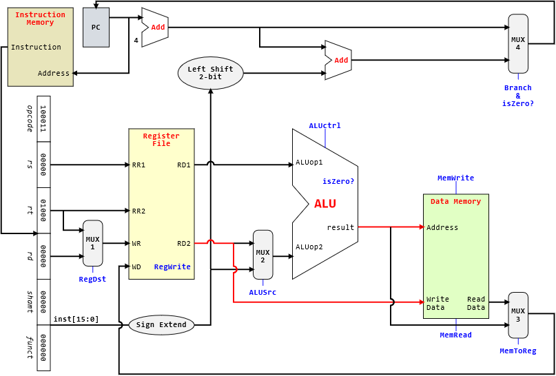] .mediumtext[ Pass the result of operation to memory. The `Data Memory` may read or write to memory but not both. This depends on the value of `MemWrite` (_for write_) and `MemRead` (_for read_). Data read will be available at read data output. ] ] --- # Stages .left-column[ #### Overview #### Fetch #### Decode #### Execute #### Memory #### Writeback ] .right-column[ .image-75[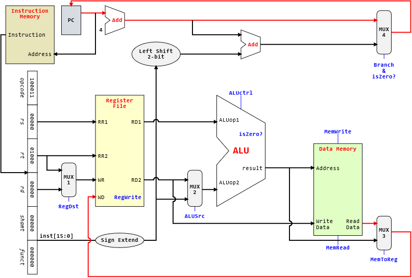] .mediumtext[ The result of operation or the data read from memory is potentially written to the register. What is written is based on the value of `MemToReg`. Note that the multiplexer is reversed here (_1 on top and 0 at the bottom_). Additionally, the `PC` is updated according to the operation which may be a branch operation (`beq`). The new PC is dependent on the `Branch` control line as well as `isZero?` result from `ALU`. ] ] --- class: center, middle # End of File