 Process
Analysis Toolkit (PAT) 3.5
Help Process
Analysis Toolkit (PAT) 3.5
Help |
BlinkApp is a simple application in the TinyOS distribution.
BlinkApp toggles the mote LED periodically, with three timers at
different periods. The application contains two .nc files: The .sn file for PAT is Blink.sn, which contains the
verification goals that are discussed in (B)Verification. (A) Simulation (B) Verification
State Definition Description #define led0ON
Sensor1.LedsC.led0 == 1; Led 0 is ON. #define led0OFF
Sensor1.LedsC.led0 == 0; Led 0 is OFF. #define led1ON
Sensor1.LedsC.led1 == 1; Led 1 is ON.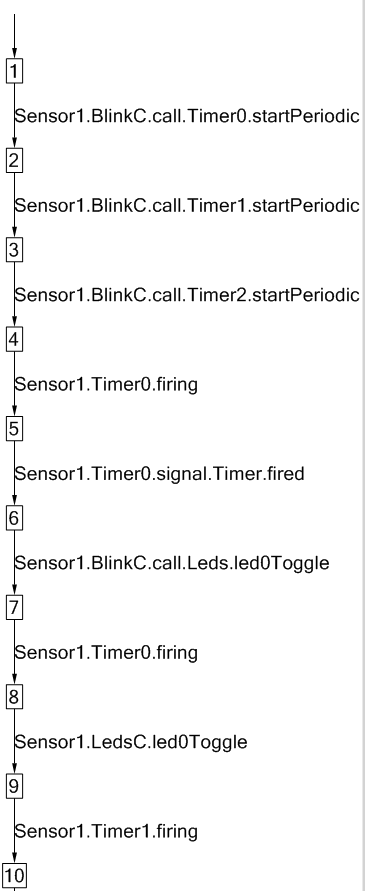 The figure on the left shows the
first few steps when simulating BlinkApp. A square stands for a configuration
(state) of the LTS, and an arrow is an transition between configurations,
labelled with the corresponding action.
The figure on the left shows the
first few steps when simulating BlinkApp. A square stands for a configuration
(state) of the LTS, and an arrow is an transition between configurations,
labelled with the corresponding action.
As an example, initially, state 1
transits to state 2 with the action Sensor1.BlinkC.call.Timer0.startPeriodic, which means that,
component BlinkC calls the command startPeriodic via the interface Timer0, which will trigger Timer0 to start timing and fire after an amount of
time. Similar are the meanings for action Sensor1.BlinkC.call.Timer1.startPeriodic and Sensor1.BlinkC.call.Timer2.startPeriodic.
State 4
transits to state 5 with the label Sensor1.Timer0.firing, which stands for an interrupt from
Timer0 meaning that Timer0
is firing. Then Timer.fired event is
signaled. This reserves the semantics of the timing service in
TinyOS.
State 5 transits to state 6 by signalling the event Timer.fired from the component Timer0. The body of the event Timer.fired is defined by BlinkC. Therefore, state 6 transits to state 7 by the event
Sensor1.BlinkC.call.Leds.led0Toggle, which is the
only statement of event Timer0.fired in component
BlinkC.
In PAT, variables are introduced to
model the status of leds. For example, variable Sensor1.LedsC.led0 keeps track of the status of
led0 of a mote.
Users can
define assertions to verify the NesC application for various properties, using
the assertion annotation language described in 3.7.1.4 Assertions. As for BlinkApp,
several assertions are defined, with states.
The following table defines
three states that are used in the assertions later.
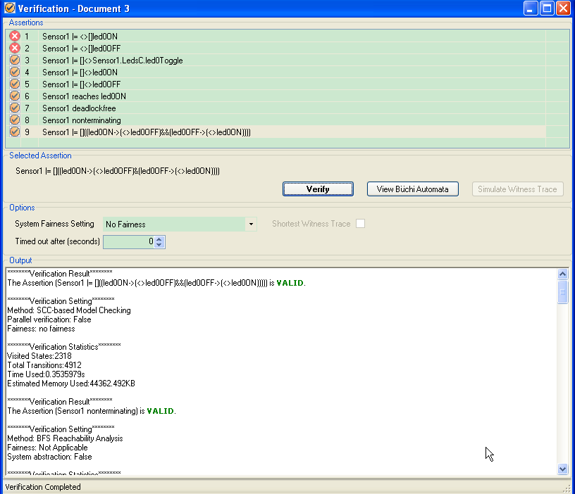
This table defines eight assertions for different properties of BlinkApp.
|
NO. |
Assertion |
Property |
|
1 |
#assert Sensor1 |= <> [] led0ON; |
Led 0 will eventually always be ON, i.e. |
|
2 |
#assert Sensor1 |= [] <> led0ON; |
Led 0 will always eventually be ON, i.e. |
|
3 |
#assert Sensor1 reaches led1ON; |
The state where led 1 is ON will be reached |
|
4 |
#assert Sensor1 deadlockfree; |
The system is deadlock free. |
|
5 |
#assert Sensor1 nonterminating; |
The system is nonterminating. |
|
6 |
#assert Sensor1 |= []<> led0OFF; |
Led 0 will always eventually be OFF, i.e. |
|
7 |
#assert Sensor1 |= |
Whenever led 0 is ON it will eventually be OFF, |
|
8 |
#assert Sensor1 |= [] <> Sensor1.LedsC.led0Toggle; |
Compoent LedsC toggles led 0 infinitely often. |
The results of verifying BlinkCApp against the assertions defined above are as the following figure. Notice that all properties are satisfied by BlinkApp, except the first one, which is reasonable.
Copyright © 2007-2012 Semantic Engineering Pte. Ltd.