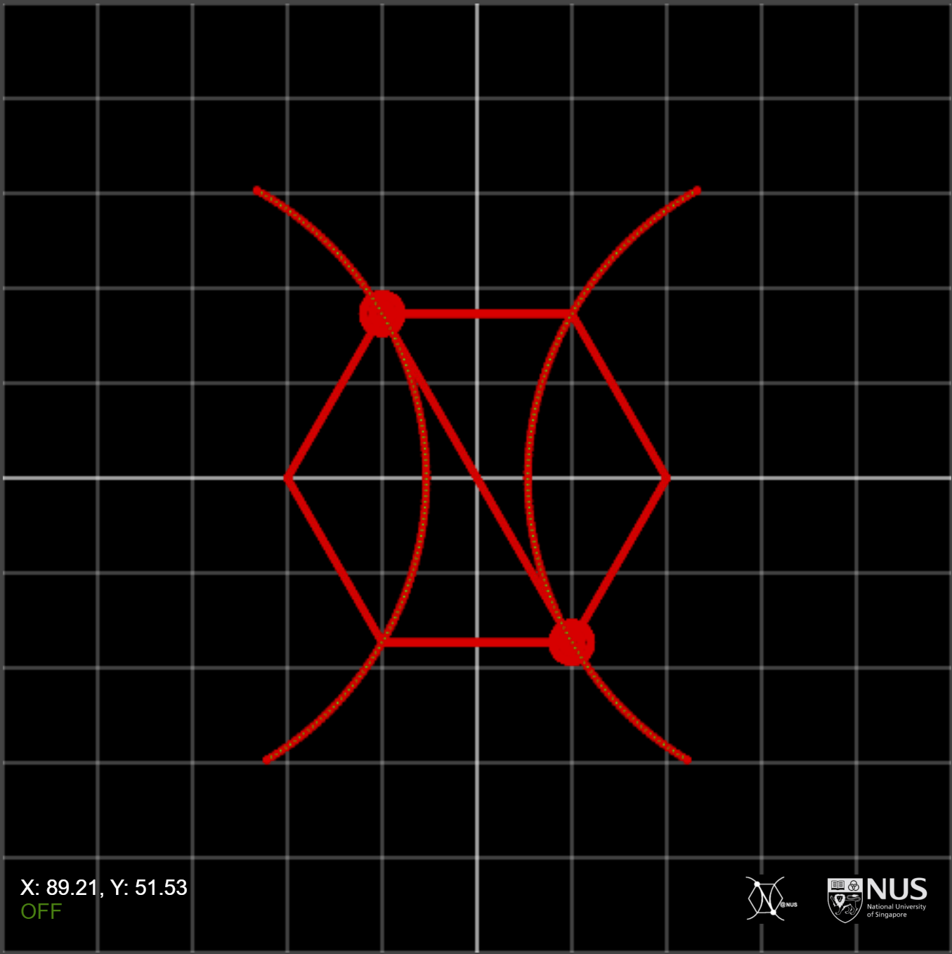
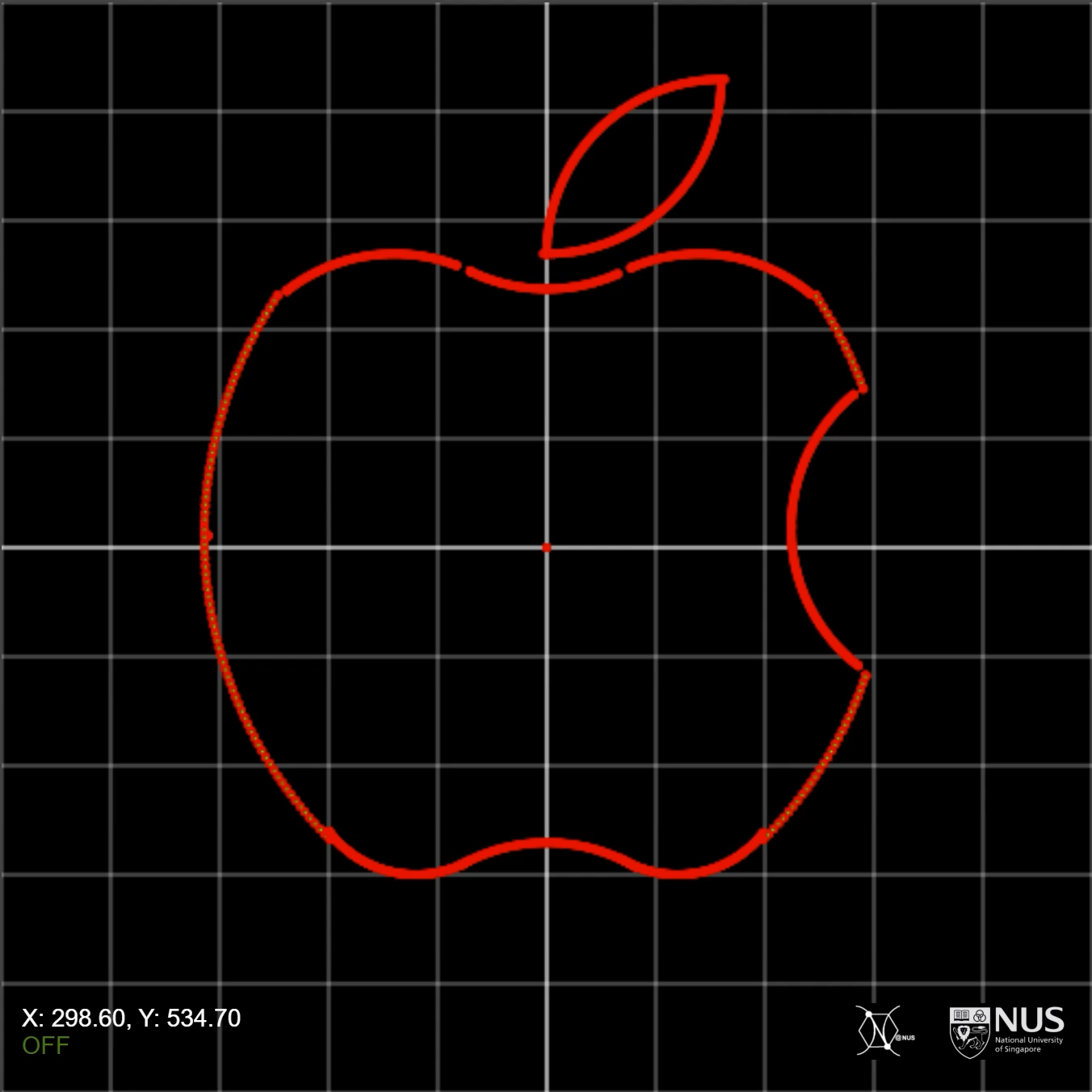
Welcome to the demonstration. Here, you will see works created by Lan Ziying using .lcs mathematical expressions and iterative functions. These expressions have successfully rendered complex geometric patterns on the PhyScript™ Integrated Laser Control Operating System (ilcos), demonstrating that with the right mathematical expressions, the system can precisely lithograph intricate 2D images. On this page, we provide the drawing code for common geometric shapes for your reference and learning, to assist you in your final engineering projects.
Initial Setup
 laser(0)
 mvAbs(150,200+100*sin<pi/3>)
 laser(255)
laser(0): Turns off the laser to move to the starting position without marking the substrate.mvAbs(150,200+100*sin<pi/3>): Moves the laser to the initial position of the top vertex of the hexagon.laser(255): Turns the laser on at maximum power to start drawing.
Drawing the Hexagon
 x=150~250 BEGIN
    mvAbs(x,200+100*sin<pi/3>)
 END
- Purpose: Draws the top horizontal side of the hexagon.
- Iteration: Moves the laser horizontally from
x=150 to x=250, keeping the y-coordinate constant.
 x=250~300 BEGIN
    mvAbs(x,200+600*sin<pi/3>-2*sin<pi/3>*x)
 END
- Purpose: Draws the upper-right side of the hexagon.
- Calculation: Uses a decreasing y-coordinate to form a diagonal line.
 x=300~250 BEGIN
    mvAbs(x,2*sin<pi/3>*x+200-600*sin<pi/3>)
 END
- Purpose: Draws the lower-right side of the hexagon.
- Calculation: Continues the diagonal line to the bottom right vertex.
 x=250~150 BEGIN
    mvAbs(x,200-100*sin<pi/3>)
 END
- Purpose: Draws the bottom horizontal side of the hexagon.
- Calculation: Moves left with a constant y-coordinate.
 x=150~100 BEGIN
    mvAbs(x,200+200*sin<pi/3>-2*sin<pi/3>*x)
 END
- Purpose: Draws the lower-left side of the hexagon.
- Calculation: Moves diagonally upwards.
 x=100~150 BEGIN
    mvAbs(x,2*sin<pi/3>*x+200-200*sin<pi/3>)
 END
- Purpose: Draws the upper-left side of the hexagon.
- Calculation: Returns to the starting point to complete the hexagon.
 x=150~250 BEGIN
    mvAbs(x,200+400*sin<pi/3>-2*sin<pi/3>*x)
 END
- Purpose: Draws a diagonal line through the hexagon.
- Calculation: Adds a dynamic element across the hexagon.
Drawing Circles
Right Circle
 laser(0)
 mvAbs(240,200-100*sin<pi/3>)
 laser(255)
 j=1~361 BEGIN
    mvAbs(250-10*cos<j*pi/180>,200-100*sin<pi/3>+10*sin<j*pi/180>)
 END
- Starting Position: Moves to the center of the right circle.
- Drawing: Uses a loop to draw a circle with a radius of 10 units.
Adjusting for the Left Circle
To draw the left circle, adjust the starting position to the left side. Use the same logic but update the x-coordinate in the mvAbs function.
 laser(0)
 mvAbs(140,200+100*sin<pi/3>)
 laser(255)
 j=1~361 BEGIN
    mvAbs(150-10*cos<j*pi/180>,200+100*sin<pi/3>+10*sin<j*pi/180>)
 END
Drawing Semicircles
Lower Semicircle
 laser(0)
 mvAbs(400-200*sin<pi/3>,200)
 laser(255)
 j=1~61 BEGIN
    mvAbs(400-200*sin<pi/3>*cos<j*pi/180>,200+200*sin<pi/3>*sin<j*pi/180>)
 END
- Position: Moves to the center of the lower semicircle.
- Drawing: Draws the first half of the semicircle using angles 1 to 60 degrees.
 laser(0)
 mvAbs(400-200*sin<pi/3>,200)
 laser(255)
 j=361~301 BEGIN
    mvAbs(400-200*sin<pi/3>*cos<j*pi/180>,200+200*sin<pi/3>*sin<j*pi/180>)
 END
- Purpose: Completes the lower semicircle by drawing the remaining arc.
Adjusting for the Upper Semicircle
For the upper semicircle, start at the appropriate coordinates above the hexagon. Update the center position and repeat the semicircle drawing logic.
 laser(0)
 mvAbs(200*sin<pi/3>,200)
 laser(255)
 j=1~61 BEGIN
    mvAbs(200*sin<pi/3>*cos<j*pi/180>,200+200*sin<pi/3>*sin<j*pi/180>)
 END


